400-8006-805

(1)Obtain the BIOS firmware package;
(2)Set the IP address of the PC and connect to the BMC management port of the server;
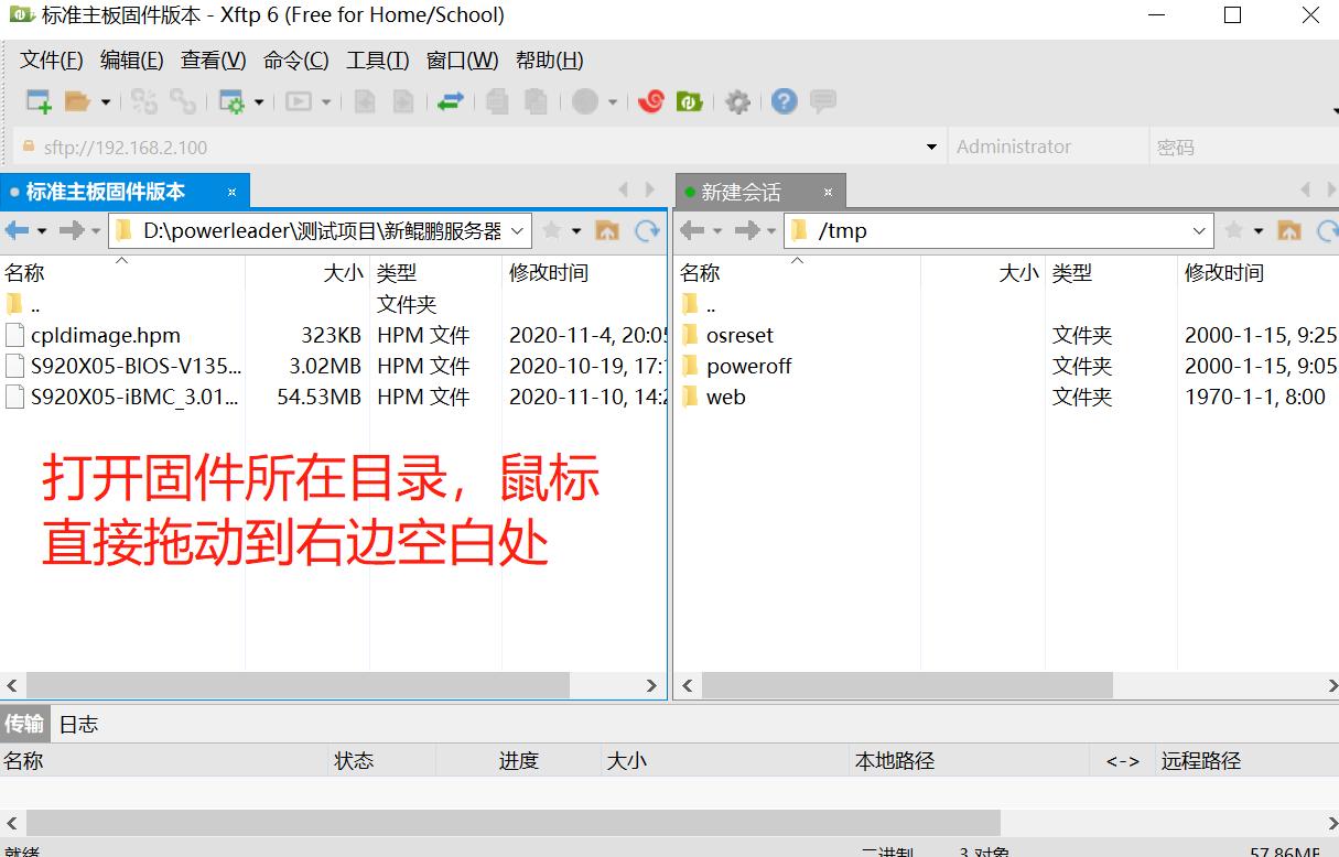
(3)Use Xftp or WinSCP to connect to the BMC of the server, upload the firmware file to the BMC directory, use Xftp as shown below:
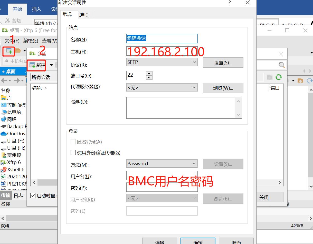
Click OK and double-click the newly created "New session", as shown in the following picture:
(4)Open CMD or other debugging tools on the computer, SSH connect to the BMC of the server, here use the PC's own CMD tool, as shown in the following figure:

If the above error occurs, open the computer C disk directory according to the prompt, modify the known_hosts file, change the code behind the last line 192.168.2.100 (BMC address) to the prompt key, save and exit after modification, ssh enter again.
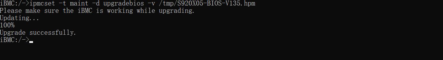
(5)Run the ipmcset -t maint -d upgradebios -v /tmp/xxx.hpm command to completely erase the BIOS upgrade. After the upgrade, the BIOS password changes to the unset state:
I. Fault symptoms
The device cannot be turned on normally. The server health indicator is green and has no alarm. It has been stuck on the logo interface for 20 minutes.
II. Troubleshooting
1. confirm whether the display is normal:
(1)Collect iBMC logs and analyze whether there are abnormal alarms.
(2)If IBMC is used, connect an independent monitor to the server and check whether any output is displayed.
2. Whether there is any modification:
Check whether the server is modified, whether the graphics card is added, and whether the non-original parts are added.
3. unless the original parts:
Remove the non-original parts and external devices (usb extended devices), boot to check whether there is a display.
4. Seek after-sales technical support:
service@glory-t.tech.
I. Problem description
The server has been ringing after boot self-test.
II. Investigation and solution
(1)Hardware failure:
The server ringing may be caused by hardware failure, such as overheating, fan failure, power supply problems, etc., may cause the server to emit alarm sounds. Solutions include checking the hardware status of the server to ensure that the fans are running properly and the temperature is appropriate, as well as checking that the power supply is stable.
(2)Power supply failure:
Power supply problems are also one of the most common causes of server chirping. Unstable voltage, insufficient power supply, etc. can cause the server to not work properly. The solution is to make sure that the server is connected to a stable power supply, check that the power lines and plugs are working properly, and make sure that the power supply is properly loaded.
(3)Hard drive failure:
Hard disk failure is also a possible cause of server chirping. A hard disk fault may cause data loss, which seriously affects the normal running of the server. The solution is to periodically check and back up hard disks on the server. If a hard disk is faulty or faulty, replace it in time.
(4)Software problems:
Sometimes, the server ringing may be caused by software problems, such as operating system errors, software conflicts, etc., which may cause the server to emit an alarm sound. The solution is to check the log files of the server to see if there are any errors or warning messages, and to update and fix the software promptly.
(5)Other reasons:
In addition to the above reasons, the server ringing may be caused by other reasons, such as network failure, memory problems, etc. The solution is to conduct a comprehensive check and diagnosis of the server, find out the problem and take appropriate measures to repair it.
III. Suggestions and summary
1. priority check whether the parts are original;
2. the second priority check the power supply, hard disk, hardware is normal;
3. seek after-sales technical support:
service@glory-t.tech.
I. Problem description
The virtual CD/DVD-ROM drive of the server cannot be mounted, and there is no response after clicking the connection.
II. Processing process
1. check the bmc and bios version found to be newer, eliminate the version problem;
2. Communicated with the site and learned that all servers on site had this problem, and eliminated hardware anomalies;
3. bmc check vmm function is enabled, check the network corresponding port 8208 is not discharged;
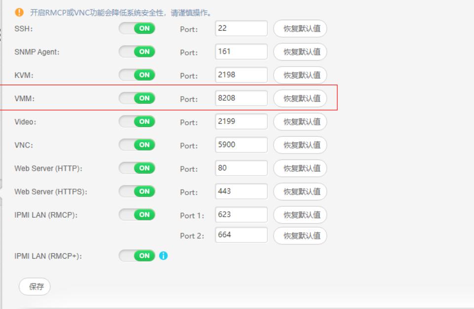
4. The problem is solved after port 8208 is disconnected.
III. Root cause
vmm corresponding port 8208 is not released.
IV. Solution
Release port 8208 corresponding to vmm.
I. Problem description
What are the modes of network card binding?
II. Second, the solution
The first kind: bond0:round robin (aggregation needs to be configured at the switch end)
Features:
(1)All links are in load balancing state. Packets are sent to each link in polling mode. Packets are sent based on per packet. ping the same IP address on the service: 1.1.1.1 Traffic is sent from both network adapters. If the traffic is sent to the two links, it indicates that the traffic is sent in polling mode based on per packet.
(2)The feature of this mode increases the bandwidth and supports fault tolerance. When a link fails, the traffic will be switched to the normal link.
Note: If the two nics are connected to different switches, there is no need to configure the switch side.
Type 2: bond1:active-backup (This mode does not require switch support)
(1) Features:
One port is in the master state, and the other is in the slave state. All traffic is processed on the master link, and there is never any traffic. When the master port goes down, the slave port takes over the master state.
Type 3: bond2:load balancing (xor)
Type 4: bond3:fault-tolerance (broadcast)
Type 5: bond4:lacp (The LACP function is enabled on the access switch)
Features:
802.3ad mode is IEEE standard, so all the peer end that implements 802.3ad can be well interoperable. The 802.3ad protocol includes aggregated auto-configuration and therefore requires very little manual configuration of the switch (it should be noted that only certain devices can use 802.3ad). The 802.3ad standard also requires frames to be passed sequentially (somewhat), so typically a single connection does not see packets out of order. The 802.3ad standard also has some disadvantages: The standard requires all devices to aggregate at the same rate and in duplex mode, and, like bonding load balancing modes except balance-rr, no connection can use the bandwidth of more than one interface.
Type 6: bond5: transmit load balancing
Seventh: bond6:adaptive load balancing (No configuration is required on the switch)
In mode6 mode, no switch is required, because the two bonding network adapters use different MAC addresses.
Tip: The common bonding modes are mode0, mode1, mode4, and mode6.